SETTING
UP THE RECORDER
Now that you have learned
about the different parts of the recorder, you can set it up.
Determine whether you want the recorder wall mounted or sitting on a bench
top.
Placing the Recorder on the Bench
Top
Figure
2-1 shows the removal of the decorative foot cover.
1. Place the recorder on its back (so it is face up).
2. Remove the clip-on foot cover by lifting up on the cover and
releasing it from the stabilizing arm at the bottom of the recorder. This
exposes the rubber feet and stabilizing arm. The rubber feet protect the
bench top surface.
 CAUTION: DO NOT ATTEMPT TO SET THE RECORDER UPRIGHT ON THE BENCH WHEN
THE CLIP-ON FOOT COVER IS IN PLACE. THE RECORDER WILL TOPPLE OVER.
3.
Swing out the stabilizing arm and extend it towards you. Figure 2-2 shows
how to swing out the stabilizing arm. Make sure the slot in the stabilizing
arm extends out the rear of the recorder. HUMIDITY pH ░C
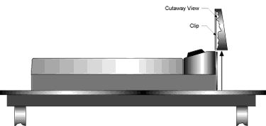
Figure 2-1. Foot Cover Removal
|
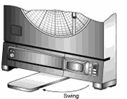
Figure
2-2.
Swiveling Stabilizing Arm
|
NOTE:
When the recorder is in normal operating position (the door is closed
and the control panel door is closed), the stabilizing arm should be pushed
to middle position (the bumps on the arm will click in place under the
recorder). Refer to Figure 2-3a. Note that the arm extends towards the
front or rear of the case. If the unit is placed on a bench top snug against
the wall, extend the stabilizing arm fully to the front of the unit. Refer
to Figure 2-3b.
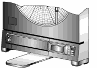
Figure
2-3a
Stabilizing Arm use for Bench Top Use
(normal position)
|
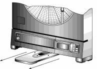 Figure
2-3b
Stabilizing Arm in Extended Position (position
when you open door)
|
Mounting the Recorder on the
Wall
To mount
the recorder on the wall, first locate the wall mounting holes using the
template provided in the wall mounting kit. Leave the decorative foot
cover (Figure 1-1, item #18) in place*. After drilling the holes, insert
the wall anchors and put in the screws, leaving 1 ┌8 inch (3 mm) between
the screw heads and the wall. Hang the recorder by positioning the two
(2) ôkeyholesö in the rear cover over the screw heads.
NOTE:
The ac adaptor has a 6 foot (2 meter) cable.
* If the decorative foot cover is not in place, go through the following
steps to reinstall the cover (if desired):
1. Place the recorder on the table (so it is front face up).
2. Roughly position the foot cover so the clips are in line with
the stabilizing arm. Gently ôstretchö the clips out and position over
the arm as shown in Figure 2-4a.
3. Once the clips are in place, gently slide down until the foot
cover is even with the front of the recorder as shown in Figure 2-4b.
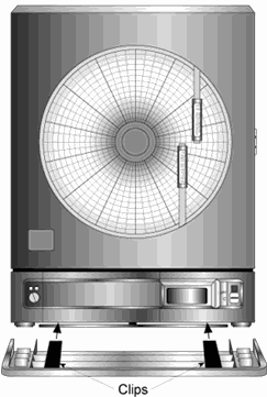
|
Figure
2-4a (on left)
Installing the Foot Cover Figure (Top
View)
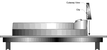
2-4b.
Installing the Foot Cover (Side View)
|
Using
Batteries
The recorder operates
on either four ôDö size batteries or on ac power. 110Vac and 220Vac adaptors
are available.
NOTE: In the
event of ac power failure, the unit will switch over to battery power
automatically. Keep a fresh set of batteries in the unit in case of power
outage, when it can be especially important to have a record of pH and
fluid temperature.
Installing
Batteries
You may power the recorder
with four ôDö size batteries. For adequate performance and battery life,
use alkaline batteries. The recorder operates full time on battery power
alone for up to one month when using fresh alkaline batteries. When replacing
batteries, we recommend that you use Duracell MN1300 ôDö size batteries
for long life and for best performance at low temperatures.
To install the
batteries
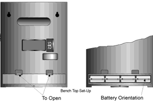
Figure 2-5. Battery Compartment and Battery
Orientation
1. Open the control panel door.
2. Turn the power switch to ôOö position.
3. Place the recorder on a soft surface front face down. Locate
the battery compartment at the bottom.
4. Open the battery compartment door by pressing down firmly on
the tabs located along the top edge.
5. Remove the battery door. 6. Install the batteries, oriented
as shown in Figure 2-5, in the battery compartment.
7. To replace the battery door, first place the bottom edge of
the door into the positioning slots in the compartment.
8. Push down on the door to snap the tabs in place.
The recorder continuously monitors the battery voltage. A ôLO BATö indication
in the upper left-hand corner of the main LCD (refer to Figure 2-6) indicates
that only one to two weeks of reliable battery operation remain, and that
the batteries need replacing within this time frame. Also, if the unit
is operating under battery power and the battery voltage is too low to
permit reliable operation, the system shuts down and displays ô---ö in
the LCD. The system may be restarted by changing the batteries or by the
re-initiation of ac power. If ac power fails, the circuitry will attempt
to automatically switch to battery backup. If viable battery power is
available, the system will operate on battery power until the batteries
fail or ac power returns. When ac power returns, the recorder will automatically
reset itself (refer to Section 8.5).
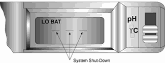
Figure 2-6. Battery Warnings
Connecting AC Power
The recorder can be ac powered using the 9Vdc, 1Amp ac adaptor supplied.
The ac power jack is located on the right side of the unit (refer to
Figure 1-1, item #6.). Make sure the power switch on the control panel
(refer to Figure 1-1, item #7) is in the ôOö position when plugging
in the ac adaptor. The adaptor cable is 6 feet (2 meters) long.
|